While this isn’t related to my game projects on this site, I’ve had the opportunity for my full-time job to experiment in the Unity3D game engine the possibility of modifying meshes, specifically to skew a series of cubes as if they were swaying in the wind. I found the experience quite fascinating, and in this article I describe what I did, my thoughts on how it relates to Unity3D, and include links to my source code in GitHub and some fun animated GIF’s.
While not a standard feature, it IS possible to modify 3D meshes in Unity.
I still haven’t quite reached the dream job where I can put my full-time efforts to making fun graphics or have the freedom to create my own stories and experiences. But I am thankful that my current position allows me to use Unity3D, which connects well with my game-making in my spare time. However, the intention to use Unity3D seemed ill-founded for the purpose: “You want meshes to modify on the fly? You want realistic physics and collisions of millions of objects? You want everything to run at video quality, but want users to be able to modify objects on a whim in the middle of viewing?” It’s a mix of what pre-rendered video is best for, but with the intention to have full interactivity, at a scale that high-end machines aren’t capable of yet. It doesn’t help that off-the-shelf game engines still don’t scale well on multi-core machines, so simply throwing money at new hardware doesn’t fix things. Everyone understands compromises will be made. Anyway, the first step was to be able to essentially skew a box. At first, I hesitated at the idea: everything I learned about workflow in Unity3D is that you could, but shouldn’t, create/modify/animate meshes inside the game engine, all of this is best handled in animation software (typically Blender3D, 3D Studio Max, or Maya) and then to import into the game as a pre-computed set of data. But in our case, the mesh modification would be based on live data, so pre-computation opportunity was limited.
But I’ve long been a strong believer in the flexibility of Unity3D. If you want to do it, there’s likely a way to do it, even if it means using oft-ignored api or otherwise finding a hack-around. It turns out it IS possible to modify mesh data in Unity during runtime, and there is some handy built-in API to do it to! But it takes a little experimentation to understand it.
Demo #1 – Repositioning a Vertex of a Mesh
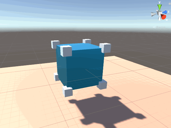
Screenshot of game while running in the editor
For the sake of my demos, we are using game logic that requires you to run the demo in the Unity3D editor. Run the game, then in the “Scene” view, start dragging around the vertex markers that appeared. The modifications will be lost after stopping the game. Compiling the game will not work on its own, as there is no added logic to select or move the vertex markers from the “Game” view.
Before we start, it is important to understand that a mesh is something a gameObject lists in its “Mesh Filter.” Without this mesh, the object would be invisible. You can read and modify vertex data on the mesh by referencing (Mesh Filter).mesh.vertices, where they are stored in a array of Vector3. But the mesh is not the same as the transform, or its values for position/rotation/scale. In the above screenshot, you can see the object position is (0,0,0), the rotation is (0,0,0) and the scale is (1,1,1), resulting in the mesh vertex markers appearing where they should. If I moved the transform to a different location, the vertex markers would still appear in the location around position (0,0,0), offset from the transform. Modifying the transform is not the same as modifying the mesh, and vice-versa. You can have some fun experimenting with this.
Anyway, to see this demo in action, take the MoveVertices.cs script (available at: https://github.com/hlynka-a/Unity3D_Mesh_Editing_Demo/blob/master/Edit_Mesh/Assets/Scripts/MoveVertices.cs) and attach it to any object with a mesh filter. Play the game, and at the start you will see vertex markers generated at each point. In the Scene view while playing, move the vertex markers around, and the mesh should correspond. See the animation below.
Animated GIF of vertex modification on 3D mesh in Unity3D
I will mention that, by default, every quad of a cube prefab in Unity3D has its own distinct vertices. This means even though you would think the faces would always be connected, it is possible to move one vertex and separate a corner from the rest of the cube, showing a hole in the mesh. For this cube, it also meant three separate vertex markers existed at each vertex, which became unwieldy if I wanted them to move together. To get around this, when generating the vertex markers, I check for duplicates based on position, and remove duplicates while providing the appropriate reference to the original marker. Feel free to comment out this part of the code to see what would happen without it.
Pretty simple, all with a script under 100 lines long. Not bad!
Demo #2 – Skewing Meshes Consistently
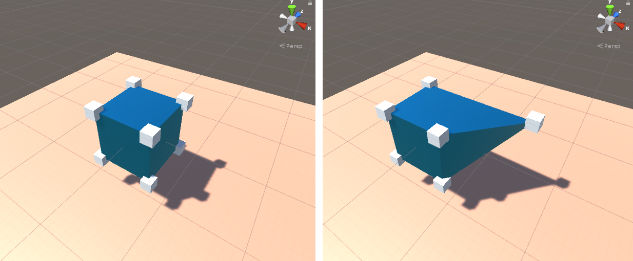
Skewing objects consistently is a bit more difficult…
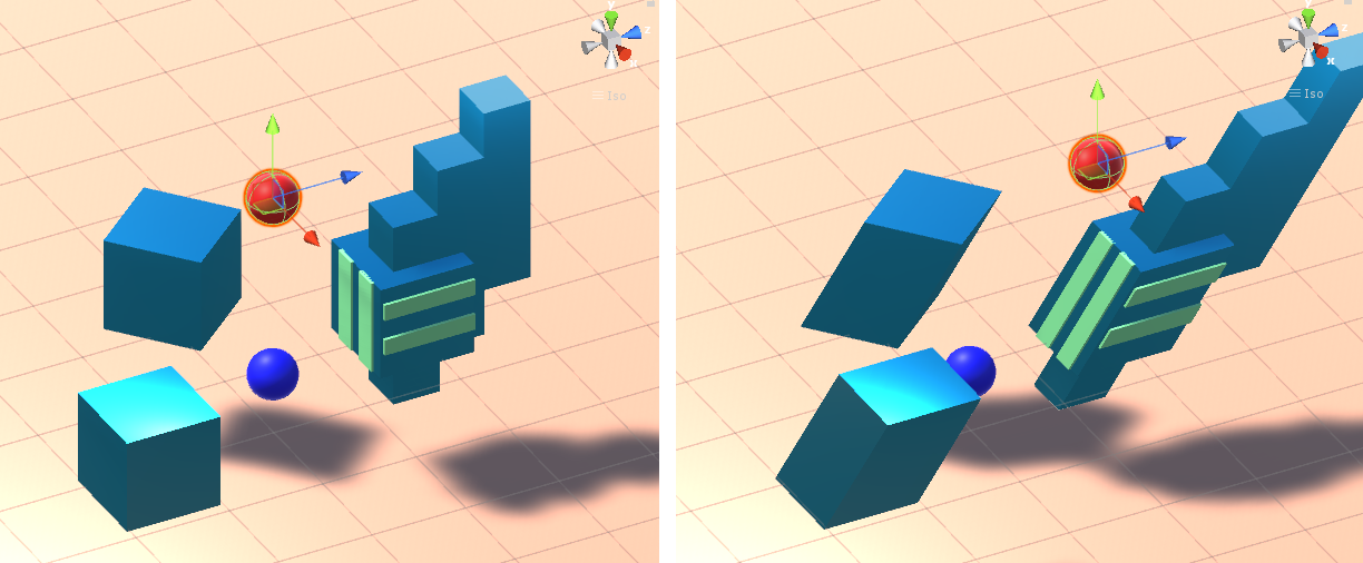
So suppose you want to skew a bunch of objects based on angles, or based on a top and bottom reference point. You could move the vertices the same was as Demo #1, having them add the displacement of the original reference points. But you wouldn’t know which vertices to modify… there is no logic to determine which are the “top four” and “bottom four” vertices, let alone how to consider more complex meshes. Also, if objects are scaled differently, it becomes clear they won’t move well together. See the above example where some objects look like they are attached to another object, when in reality they are being modified in the same manner as the other meshes.
To get around this, I made a script to calculate the angle between the red and blue reference points at every frame, and to send that information to each object for them to independently handle how to be skewed. It involves calculating the angle based on x/y/z positions, and generating an appropriate rotation matrix based on the scale and position of the object being modified (matrices? Wow, that takes me back to school! Don’t forget Linear Algebra and Intro to Computer Graphics if you want to make games!). Also relating to computer graphics, I quickly rotate an object to (0,0,0) before making the transformation, then rotate it back, all the while the user wouldn’t notice, a common trick in OpenGL. The skew effect also occurs from the center of each object, so I added logic to reposition the transform after skewing to make it seem like the base of the object stayed in line with the blue marker, and to also allow to you move either the red or blue marker for an appropriate effect.
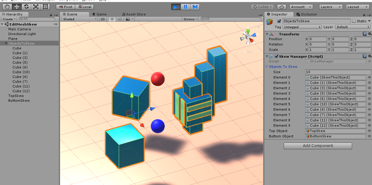
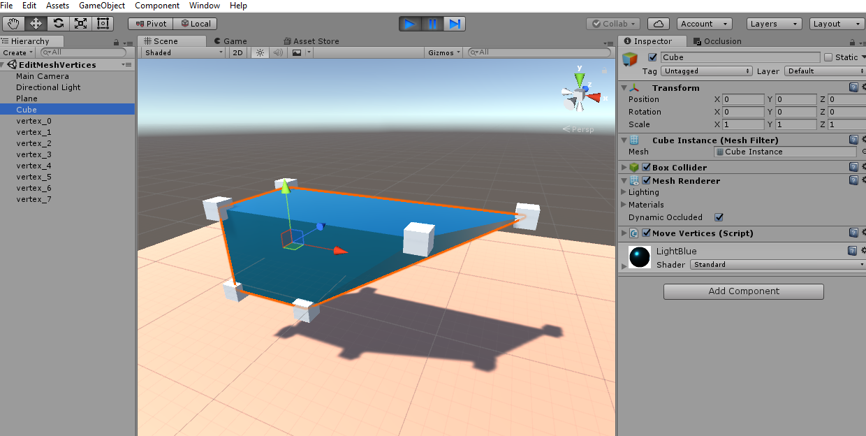
A screenshot to give an idea of the setup in the Unity3D editor
See the above screenshot to get an idea of how the scene was organized: there is an object with a “SkewManager.cs” script (available at: https://github.com/hlynka-a/Unity3D_Mesh_Editing_Demo/blob/master/Edit_Mesh/Assets/Scripts/SkewManager.cs). Add to the objects to be modified a “SkewThisObject.cs” instance (available at: https://github.com/hlynka-a/Unity3D_Mesh_Editing_Demo/blob/master/Edit_Mesh/Assets/Scripts/SkewThisObject.cs). Add the objects to the array list in the inspector (the script will otherwise search for children with the script by default if you leave the list empty). Add a reference to the marker objects to the SkewManager script in the inspector. Play the game and start moving the red/blue balls around in the Scene view. You should get something like the animations below:
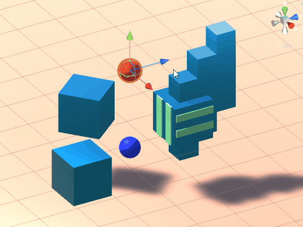
Animated GIF of skewing in action
Animated GIF – notice that the angles of all the shapes skew consistently.
This required a lot of trial-and-error to understand that math, and I might be missing a few details for this to work seamlessly with all objects (see the next section for more details on limitations). Notice that the angles are consistent on all shapes, no matter their scale or position, and that they move in unison with respect to the global position of the reference markers.
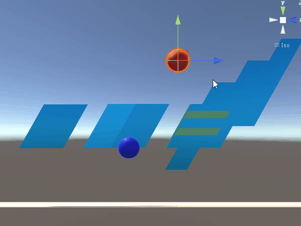
A fun trick is to position a mesh with a clear top/bottom face directly in the middle of the red and blue markers, and to rescale the transform to fit the markers directly in the center of each face. It will look like you are directly positioning the x/z coordinates of the face! And there’s no reason you can’t have several separate reference sets each modifying their own objects!
Why Doesn’t Unity3D Have This As A Built-In Feature?
Aside from the ability to subdivide (add vertices) and to remove vertices or faces, what I have here is a good foundation that can be used to create a built-in mesh editor. Of course, you would want to make sure modifications can be saved and reused rather than destroyed upon ending a game (editor features like this have been built before, so I’m certain it is possible, I just got lazy and stopped). Some third-party developers also provide more-complete paid options through the Unity asset store.
But if it is really this easy, why hasn’t Unity implemented something like this already and included in with its release?
With the first demo, simply moving vertices can cause some problems. Remember each is connected to a triangle, and how those triangles rescale and rotate is not always trivial. The way those two triangles per square are aligned makes a difference. If there were four triangles per face, such that it made a symmetrical structure, then it might be easier to utilize, but then more memory would be needed. And we’re talking about simple squares on a cube, for more complex meshes things can get out of hand fast. You would need a more robust set of tools to separate and combine meshes, rotate individual faces, reset texture mapping, all with an easy interface. I think that’s why Unity opted to ask developers to continue using tried-and-true modelling software in their workflow, to prevent the game engine from getting to crowded.
With the second demo, there’s a serious issue related to “transform.lossyScale” and Unity’s built-in rotation calculations. Unlike position and rotation, there is no way to reference the exact “global scale” of an object’s transform. Instead, lossyScale is provided, and like the name suggests, the data it provides can be lossy (read: occasionally inaccurate). LossyScale tends to be drastically inaccurate if the object is a child of a rotated parent object. Give it a try: create a gameobject, duplicate it, put one in a rotated parent object, then print out the lossyScale of both. The objects should look identical. Keep trying to see how often the scales match (in my case, I saw some pretty wild discrepancies). It turns out this has something to do with position/rotation/scale all being calculated with floating-point precision rather than double. Apparently this is common in game engines like “Unreal” as well, possibly because of limitations in most GPU’s. Aside from lossyScale, remember that we are modifying a mesh, which is separate from the values of the transform. So just because a transform is rotated does not mean the mesh will correspond to it. If the scaling of the transform is uniform (1,1,1), then this isn’t really an issue, since the axis value is the same no matter which you use. Otherwise, you’ll still see the object skew, but not at the same angle as the other shapes.
So for good results for consistent skewing, the game objects to be modified ideally should: {{1) have (0, 0, 0) rotation, OR 2) have (1, 1, 1) scaling}, AND 3) not be a child of a parent that does not satisfy both 1) and 2)}. Give it a try yourself and see. Maybe some extra math can help get around these limitations. If you want to share your ideas, feel free to leave a comment below.
The efficiency of skewing objects like this isn’t all that great either. It relies of sin/cos/tan to calculate angles, which with reference to this handy article, is not ideal to run often in every frame. As it is, I was able to test modifying about 2,000 separate objects while getting barely 2 fps on my admittedly-not-suited-for-gaming laptop. In my case, I was able to get better performance by combining meshes ahead of time, resulting in the same about of vertices, but less meshes to read/write from, and getting about 30 fps for about 20 more-complex meshes. There’s probably a better way to calculate the angle between two objects, if anyone knows some efficient tricks, I also welcome comments on that below.
Ultimately, for my purposes I think it might be more efficient to have used OpenGL instead of Unity3D. Thankfully, Unity3D does in fact have a “GL” library to allow for using it within the engine, although it limits some interaction such as collision detection or shading. I better get back to work.
Download Links:
GitHub link to this Unity3D project, including scripts and 2 scenes with above examples: https://github.com/hlynka-a/Unity3D_Mesh_Editing_Demo
I hope this was a useful beginner’s guide for you! I sure learned a lot!
Side Note: The GIF’s were created using free software called “ScreenToGif.” I remember a time when recording your screen wasn’t easy, and most free options were terrible. But this was easy to install, easy to use, and has a great set of options to created animated GIF’s or video of your screen. It won’t be game-capture quality, but for recording short accompanying animations for tutorials or lectures, it is as good as I can imagine. Kudos to developer Nicke Manarin for a great product, I’d recommend it to anyone and everyone as essential software.